Output will show the Slot ID, Usage and then the Bus Address
Designation: CPU SLOT1 PCI-E 4.0 X16
Current Usage: Available
Bus Address: 0000:ff:00.0
Designation: CPU SLOT2 PCI-E 4.0 X8
Current Usage: In Use
Bus Address: 0000:41:00.0
Designation: CPU SLOT3 PCI-E 4.0 X16
Current Usage: In Use
Bus Address: 0000:c1:00.0
Designation: CPU SLOT4 PCI-E 4.0 X8
Current Usage: Available
Bus Address: 0000:ff:00.0
Designation: CPU SLOT5 PCI-E 4.0 X16
Current Usage: In Use
Bus Address: 0000:c2:00.0
Designation: CPU SLOT6 PCI-E 4.0 X16
Current Usage: Available
Bus Address: 0000:ff:00.0
Designation: CPU SLOT7 PCI-E 4.0 X16
Current Usage: In Use
Bus Address: 0000:81:00.0
Designation: PCI-E M.2-M1
Current Usage: Available
Bus Address: 0000:ff:00.0
Designation: PCI-E M.2-M2
Current Usage: Available
Bus Address: 0000:ff:00.0
We can use lspci -s #BusAddress# to locate whats installed on each slot
Im sure there is a much more elegant way to do this, but this worked as a quick ish way to find what i needed. if you know a better way please share in the comments
just something that came up while setting up a monitoring script using mailx, figured ill note it down here so i can get it to easily later when I need it š
Important prerequisites
You need to enable smtp basic Auth on Office 365 for the account used for authentication
Create an App password for the user account
nssdb folder must be available and readable by the user running the mailx command
Assuming all of the above prerequisite are $true we can proceed with the setup
Install mailx
RHEL/Alma linux
sudo dnf install mailx
NSSDB Folder
make sure the nssdb folder must be available and readable by the user running the mailx command
certutil -L -d /etc/pki/nssdb
The Output might be empty, but that’s ok; this is there if you need to add a locally signed cert or another CA cert manually, Microsoft Certs are trusted by default if you are on an up to date operating system with the local System-wide Trust Store
Append/prepend the following lines and Comment out or remove the same lines already defined on the existing config files
set smtp=smtp.office365.com
set smtp-auth-user=###[email protected]###
set smtp-auth-password=##Office365-App-password#
set nss-config-dir=/etc/pki/nssdb/
set ssl-verify=ignore
set smtp-use-starttls
set from="###[email protected]###"
This is the bare minimum needed other switches are located here – link
-v switch will print the verbos debug log to console
Connecting to 52.96.40.242:smtp . . . connected.
220 xxde10CA0031.outlook.office365.com Microsoft ESMTP MAIL Service ready at Sun, 6 Aug 2023 22:14:56 +0000
>>> EHLO vls-xxx.multicastbits.local
250-MN2PR10CA0031.outlook.office365.com Hello [167.206.57.122]
250-SIZE 157286400
250-PIPELINING
250-DSN
250-ENHANCEDSTATUSCODES
250-STARTTLS
250-8BITMIME
250-BINARYMIME
250-CHUNKING
250 SMTPUTF8
>>> STARTTLS
220 2.0.0 SMTP server ready
>>> EHLO vls-xxx.multicastbits.local
250-xxde10CA0031.outlook.office365.com Hello [167.206.57.122]
250-SIZE 157286400
250-PIPELINING
250-DSN
250-ENHANCEDSTATUSCODES
250-AUTH LOGIN XOAUTH2
250-8BITMIME
250-BINARYMIME
250-CHUNKING
250 SMTPUTF8
>>> AUTH LOGIN
334 VXNlcm5hbWU6
>>> Zxxxxxxxxxxxc0BmdC1zeXMuY29t
334 UGsxxxxxmQ6
>>> c2Rxxxxxxxxxxducw==
235 2.7.0 Authentication successful
>>> MAIL FROM:<###[email protected]###>
250 2.1.0 Sender OK
>>> RCPT TO:<[email protected]>
250 2.1.5 Recipient OK
>>> DATA
354 Start mail input; end with <CRLF>.<CRLF>
>>> .
250 2.0.0 OK <[email protected]> [Hostname=Bsxsss744.namprd11.prod.outlook.com]
>>> QUIT
221 2.0.0 Service closing transmission channel
Now you can use this in your automation scripts or timers using the mailx command
#!/bin/bash
log_file="/etc/app/runtime.log"
recipient="[email protected]"
subject="Log file from /etc/app/runtime.log"
# Check if the log file exists
if [ ! -f "$log_file" ]; then
echo "Error: Log file not found: $log_file"
exit 1
fi
# Use mailx to send the log file as an attachment
echo "Sending log file..."
mailx -s "$subject" -a "$log_file" -r "[email protected]" "$recipient" < /dev/null
echo "Log file sent successfully."
The above commands change the file’s owner and group to root, then set the file permissions to 600, which means only the owner (root) has read and write permissions and other users have no access to the file.
Use Environment Variables: Avoid storing sensitive information like passwords directly in the mail.rc file, consider using environment variables for sensitive data and reference those variables in the configuration.
For example, in the mail.rc file, you can set:
set smtp-auth-password=$MY_EMAIL_PASSWORD
You can set the variable using another config file or store it in the Ansible vault during runtime or use something like Hashicorp.
Sure, I would just use Python or PowerShell core, but you will run into more locked-down environments like OCI-managed DB servers with only Mailx is preinstalled and the only tool you can use š
the Fact that you are here means you are already in the same boat. Hope this helped… until next time
After looking around for a few hours digging in to the logs i figured out the issue, hopefully this helps some one else our there in the situation save some time.
Make sure the IPVS mode is enabled on the cluster configuration
If you are using :
RKE2 – edit the cluster.yaml file
RKE1 – Edit the cluster configuration from the rancher UI > Cluster management > Select the cluster > edit configuration > edit as YAML
Locate the services field under rancher_kubernetes_engine_config and add the following options to enable IPVS
Make sure the Kernel modules are enabled on the nodes running control planes
Background
Example Rancher – RKE1 cluster
sudo docker ps | grep proxy # find the container ID for kubproxy
sudo docker logs ####containerID###
0313 21:44:08.315888 108645 feature_gate.go:245] feature gates: &{map[]}
I0313 21:44:08.346872 108645 proxier.go:652] "Failed to load kernel module with modprobe, you can ignore this message when kube-proxy is running inside container without mounting /lib/modules" moduleName="nf_conntrack_ipv4"
E0313 21:44:08.347024 108645 server_others.go:107] "Can't use the IPVS proxier" err="IPVS proxier will not be used because the following required kernel modules are not loaded: [ip_vs_lc]"
Kubproxy is trying to load the needed kernel modules and failing to enable IPVS
if you want to prevent directory traversal we need to setup chroot with vsftpd (not covered on this KB)
For the demo I just used Unencrypted FTP on port 21 to keep things simple, Please utilize SFTP with the letsencrypt certificate for better security. i will cover this on another article and link it here
Update and Install packages we need
sudo dnf update
sudo dnf install net-tools lsof unzip zip tree policycoreutils-python-utils-2.9-20.el8.noarch vsftpd nano setroubleshoot-server -y
Setup Groups and Users and security hardening
if you want to prevent directory traversal we need to setup chroot with vsftpd (not covered on this KB)
Create the Service admin account
sudo useradd ftpadmin
sudo passwd ftpadmin
Create the group
sudo groupadd FTP_Root_RW
Create FTP only user shell for the FTP users
echo -e '#!/bin/sh\necho "This account is limited to FTP access only."' | sudo tee -a /bin/ftponly
sudo chmod a+x /bin/ftponly
echo "/bin/ftponly" | sudo tee -a /etc/shells
Create FTP users
sudo useradd ftpuser01 -m -s /bin/ftponly
sudo useradd ftpuser02 -m -s /bin/ftponly
user passwd ftpuser01
user passwd ftpuser02
Add the users to the group
sudo usermod -a -G FTP_Root_RW ftpuser01
sudo usermod -a -G FTP_Root_RW ftpuser02
sudo usermod -a -G FTP_Root_RW ftpadmin
Disable SSH Access for the FTP users.
Edit sshd_config
sudo nano /etc/ssh/sshd_config
Add the following line to the end of the file
DenyUsers ftpuser01 ftpuser02
Open ports on the VM Firewall
sudo firewall-cmd --permanent --add-port=20-21/tcp
#Allow the passive Port-Range we will define it later on the vsftpd.conf
sudo firewall-cmd --permanent --add-port=60000-65535/tcp
#Reload the ruleset
sudo firewall-cmd --reload
Setup the Second Disk for FTP DATA
Attach another disk to the VM and reboot if you haven’t done this already
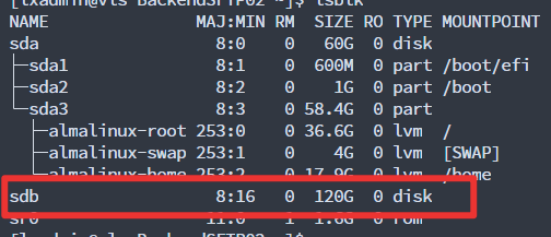
lsblk to check the current disks and partitions detected by the system
sudo mv /etc/vsftpd/user_list /etc/vsftpd/user_listBackup
echo "ftpuser01" | sudo tee -a /etc/vsftpd/user_list
echo "ftpuser02" | sudo tee -a /etc/vsftpd/user_list
instead of putting our hands up and disabling SElinux, we are going to setup the policies correctly
Find the available policies using getsebool -a | grep ftp
getsebool -a | grep ftp
ftpd_anon_write --> off
ftpd_connect_all_unreserved --> off
ftpd_connect_db --> off
ftpd_full_access --> off
ftpd_use_cifs --> off
ftpd_use_fusefs --> off
ftpd_use_nfs --> off
ftpd_use_passive_mode --> off
httpd_can_connect_ftp --> off
httpd_enable_ftp_server --> off
tftp_anon_write --> off
tftp_home_dir --> off
[lxadmin@vls-BackendSFTP02 _logs]$
[lxadmin@vls-BackendSFTP02 _logs]$
[lxadmin@vls-BackendSFTP02 _logs]$ getsebool -a | grep ftp
ftpd_anon_write --> off
ftpd_connect_all_unreserved --> off
ftpd_connect_db --> off
ftpd_full_access --> off
ftpd_use_cifs --> off
ftpd_use_fusefs --> off
ftpd_use_nfs --> off
ftpd_use_passive_mode --> off
httpd_can_connect_ftp --> off
httpd_enable_ftp_server --> off
tftp_anon_write --> off
tftp_home_dir --> off
Set SELinux boolean values
sudo setsebool -P ftpd_use_passive_mode on
sudo setsebool -P ftpd_use_cifs on
sudo setsebool -P ftpd_full_access 1
"setsebool" is a tool for setting SELinux boolean values, which control various aspects of the SELinux policy.
"-P" specifies that the boolean value should be set permanently, so that it persists across system reboots.
"ftpd_use_passive_mode" is the name of the boolean value that should be set. This boolean value controls whether the vsftpd FTP server should use passive mode for data connections.
"on" specifies that the boolean value should be set to "on", which means that vsftpd should use passive mode for data connections.
Enable ftp_home_dir --> on if you are using chroot
Add a new file context rule to the system.
sudo semanage fcontext -a -t public_content_rw_t "/FTP_DATA_DISK/FTP_Root/(/.*)?"
"fcontext" is short for "file context", which refers to the security context that is associated with a file or directory.
"-a" specifies that a new file context rule should be added to the system.
"-t" specifies the new file context type that should be assigned to files or directories that match the rule.
"public_content_rw_t" is the name of the new file context type that should be assigned to files or directories that match the rule. In this case, "public_content_rw_t" is a predefined SELinux type that allows read and write access to files and directories in public directories, such as /var/www/html.
"/FTP_DATA_DISK/FTP_Root/(/.)?" specifies the file path pattern that the rule should match. The pattern includes the "/FTP_DATA_DISK/FTP_Root/" directory and any subdirectories or files beneath it. The regular expression "/(.)?" matches any file or directory name that may follow the "/FTP_DATA_DISK/FTP_Root/" directory path.
In summary, this command sets the file context type for all files and directories under the "/FTP_DATA_DISK/FTP_Root/" directory and its subdirectories to "public_content_rw_t", which allows read and write access to these files and directories.
Reset the SELinux security context for all files and directories under the “/FTP_DATA_DISK/FTP_Root/”
sudo restorecon -Rvv /FTP_DATA_DISK/FTP_Root/
"restorecon" is a tool that resets the SELinux security context for files and directories to their default values.
"-R" specifies that the operation should be recursive, meaning that the security context should be reset for all files and directories under the specified directory.
"-vv" specifies that the command should run in verbose mode, which provides more detailed output about the operation.
"/FTP_DATA_DISK/FTP_Root/" is the path of the directory whose security context should be reset.
Setup Fail2ban
Install fail2ban
sudo dnf install fail2ban
Create the jail.local file
This file is used to overwrite the config blocks in /etc/fail2ban/fail2ban.conf
journalctl -u fail2ban will help you narrow down any issues with the service
Testing
sudo tail -f /var/log/fail2ban.log
Fail2ban injects and manages the following rich rules
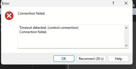
Client will fail to connect using FTP until the ban is lifted
Remove the ban IP list
#get the list of banned IPs
sudo fail2ban-client get vsftpd banned
#Remove a specific IP from the list
sudo fail2ban-client set vsftpd unbanip <IP>
#Remove/Reset all the the banned IP lists
sudo fail2ban-client unban --all
This should get you up and running, For the demo I just used Unencrypted FTP on port 21 to keep things simple, Please utilize SFTP with the letsencrypt certificate for better security. i will cover this on another article and link it here
If you found this page you already know why you are looking for this, your server /dev/mapper/cs-root is filled due to /var/lib/docker taking up most of the space
Yes, you can change the location of the Docker overlay2 storage directory by modifying the daemon.json file. Here’s how to do it:
Open or create the daemon.json file using a text editor:
sudo nano /etc/docker/daemon.json
{
"data-root": "/path/to/new/location/docker"
}
Replace “/path/to/new/location/docker” with the path to the new location of the overlay2 directory.
If the file already contains other configuration settings, add the "data-root" setting to the file under the "storage-driver" setting:
Root CA cert is pushed out to all Servers/Desktops – This happens by default
Contents
Setup CA Certificate template
Deploy Auto-enrolled Certificates via Group Policy
Powershell logon script to set the WinRM listener
Deploy the script as a logon script via Group Policy
Testing
1 – Setup CA Certificate template to allow Client Servers/Desktops to checkout the certificate from the CA
Connect to the The Certification Authority Microsoft Management Console (MMC)
Navigate to Certificate Templates > Manage
On the “Certificate templates Console” window > Select Web Server > Duplicate Template
Under the new Template window Set the following attributes
General – Pick a Name and Validity Period – This is up to you
Compatibility – Set the compatibility attributes (You can leave this on the default values, It up to you)
Subject Name – Set ‘Subject Name’ attributes (Important)
Security – Add “Domain Computers” Security Group and Set the following permissions
Read – Allow
Enroll – Allow
Autoenroll – Allow
Click “OK” to save and close out of “Certificate template console”
Issue to the new template
Go back to the “The Certification Authority Microsoft Management Console” (MMC)
Under templates (Right click the empty space) > Select New > Certificate template to Issue
Under the Enable Certificate template window > Select the Template you just created
Allow few minutes for ADDS to replicate and pick up the changes with in the forest
2 – Deploy Auto-enrolled Certificates via Group Policy
Create a new GPO
Windows Settings > Security Settings > Public Key Policies/Certificate Services Client – Auto-Enrollment Settings
Link the GPO to the relevant OU with in your ADDS environment
Note – You can push out the root CA cert as a trusted root certificate with this same policy if you want to force computers to pick up the CA cert,
Testing
If you need to test it gpupdate/force or reboot your test machine, The Server VM/PC will pickup a certificate from ADCS PKI
3 – Powershell logon script to set the WINRM listener
Dry run
Setup the log file
Check for the Certificate matching the machines FQDN Auto-enrolled from AD CS
If exist
Set up the HTTPS WInRM listener and bind the certificate
Write log
else
Write log
#Malinda Rathnayake- 2020
#
#variable
$Date = Get-Date -Format "dd_MM_yy"
$port=5986
$SessionRunTime = Get-Date -Format "dd_yyyy_HH-mm"
#
#Setup Logs folder and log File
$ScriptVersion = '1.0'
$locallogPath = "C:\_Scripts\_Logs\WINRM_HTTPS_ListenerBinding"
#
$logging_Folder = (New-Item -Path $locallogPath -ItemType Directory -Name $Date -Force)
$ScriptSessionlogFile = New-Item $logging_Folder\ScriptSessionLog_$SessionRunTime.txt -Force
$ScriptSessionlogFilePath = $ScriptSessionlogFile.VersionInfo.FileName
#
#Check for the the auto-enrolled SSL Cert
$RootCA = "Company-Root-CA" #change This
$hostname = ([System.Net.Dns]::GetHostByName(($env:computerName))).Hostname
$certinfo = (Get-ChildItem -Path Cert:\LocalMachine\My\ |? {($_.Subject -Like "CN=$hostname") -and ($_.Issuer -Like "CN=$RootCA*")})
$certThumbprint = $certinfo.Thumbprint
#
#Script-------------------------------------------------------
#
#Remove the existing WInRM Listener if there is any
Get-ChildItem WSMan:\Localhost\Listener | Where -Property Keys -eq "Transport=HTTPS" | Remove-Item -Recurse -Force
#
#If the client certificate exists Setup the WinRM HTTPS listener with the cert else Write log
if ($certThumbprint){
#
New-Item -Path WSMan:\Localhost\Listener -Transport HTTPS -Address * -CertificateThumbprint $certThumbprint -HostName $hostname -Force
#
netsh advfirewall firewall add rule name="Windows Remote Management (HTTPS-In)" dir=in action=allow protocol=TCP localport=$port
#
Add-Content -Path $ScriptSessionlogFilePath -Value "Certbinding with the HTTPS WinRM HTTPS Listener Completed"
Add-Content -Path $ScriptSessionlogFilePath -Value "$certinfo.Subject"}
else{
Add-Content -Path $ScriptSessionlogFilePath -Value "No Cert matching the Server FQDN found, Please run gpupdate/force or reboot the system"
}
Script is commented with Explaining each section (should have done functions but i was pressed for time, never got around to do it, if you do fix it up and improve this please let me know in the comments :D)
5 – Deploy the script as a logon script via Group Policy
Setup a GPO and set this script as a logon Powershell script
Im using a user policy with GPO Loop-back processing set to Merge applied to the server OU
Testing
To confirm WinRM is listening on HTTPS, type the following commands:
winrm enumerate winrm/config/listener
Winrm get http://schemas.microsoft.com/wbem/wsman/1/config
Received the following error from the Azure AD stating that Password Synchronization was not working on the tenant.
When i manually initiate a delta sync, i see the following logs
"The Specified Domain either does not exist or could not be contacted"
(click to enlarge)
Checked the following
Restarted ADsync Services
Resolve the ADDS Domain FQDN and DNS – Working
Test required ports for AD-sync using portqry – issues with the Primary ADDS server defined on the DNS values
Root Cause
Turns out the Domain controller Defined as the primary DNS value was pointing was going thorough updates, its responding on the DNS but doesn’t return any data (Brown-out state)
Assumption
when checking DNS since the DNS server is connecting, Windows doesn’t check the secondary and tertiary servers defined under DNS servers.
This might happen if you are using a ADDS server via a S2S tunnel/MPLS when the latency goes high
Resolution
Check make sure your ADDS-DNS servers defined on AD-SYNC server are alive and responding
in my case i just updated the “Primary” DNS value with the umbrella Appliance IP (this act as a proxy and handle the fail-over)
Update Manager is bundled in the vCenter Server Appliance since version 6.5, itās a plug-in that runs on the vSphere Web Client. we can use the component to
patch/upgrade hosts
deploy .vib files within the V-Center
Scan your VC environment and report on any out of compliance hosts
Hardcore/Experienced VMware operators will scoff at this article, but I have seen many organizations still using ILO/IDRAC to mount an ISO to update hosts and they have no idea this function even exists.
Now thatās out of the way Letās get to the how-to part of this
In Vcenter click the “Menu” and drill down to the “Update Manager”
This Blade will show you all the nerd knobs and overview of your current Updates and compliance levels
Click on the “Baselines” Tab
You will have two predefined baselines for security patches created by the Vcenter, let keep that aside for now
Navigate to the “ESXi Images” Tab, and Click “Import”
Once the Upload is complete, Click on “New Baseline”
Fill in the Name and Description that makes sense to anyone that logs in and click Next
Select the image you just Uploaded before on the next Screen and continue through the wizard and complete it
Note – If you have other 3rd party software for ESXI you can create seprate baselines for those and use baseline Groups to push out upgrades and vib files at the same time
Now click the “Menu” and Navigate Backup to “Hosts and Clusters”
Now you can apply the Baseline this at various levels within the Vcenter Hierarchy
Vcenter | DataCenter | Cluster | Host
Depending on your use case pick the right level
Excerpt from the KB
For ESXi hosts in a cluster, the remediation process is sequential by default. With Update Manager, you can select to run host remediation in parallel.
When you remediate a cluster of hosts sequentially and one of the hosts fails to enter maintenance mode, Update Manager reports an error, and the process stops and fails. The hosts in the cluster that are remediated stay at the updated level. The ones that are not remediated after the failed host remediation are not updated. If a host in a DRS enabled cluster runs a virtual machine on which Update Manager or vCenter Server are installed, DRS first attempts to migrate the virtual machine running vCenter Server or Update Manager to another host so that the remediation succeeds. In case the virtual machine cannot be migrated to another host, the remediation fails for the host, but the process does not stop. Update Manager proceeds to remediate the next host in the cluster.
The host upgrade remediation of ESXi hosts in a cluster proceeds only if all hosts in the cluster can be upgraded.
Remediation of hosts in a cluster requires that you temporarily disable cluster features such as VMware DPM and HA admission control. Also, turn off FT if it is enabled on any of the virtual machines on a host, and disconnect the removable devices connected to the virtual machines on a host, so that they can be migrated with vMotion. Before you start a remediation process, you can generate a report that shows which cluster, host, or virtual machine has the cluster features enabled.
Creating a persistent scratch location for ESXi – https://kb.vmware.com/s/article/1033696
Cause 2
Hardware is not compatible,
I had this issue due to 6.7 dropping support for an LSI Raid card on an older firmware, you need to do some foot work and check the log files to figure out why its failing
So recently I ran into this annoying error message with Exchange 2016 CU11 Update.
Environment info-
Exchange 2016 upgrade from CU8 to CU11
Exchange binaries are installed under D:\Microsoft\Exchange_Server_V15\..
Microsoft.PowerShell.Commands.GetItemCommand.ProcessRecord()". [12/04/2018 16:41:43.0233] [1] [ERROR] Cannot find path 'D:\Microsoft\Exchange_Server_V15\UnifiedMessaging\grammars' because it does not exist. [12/04/2018 16:41:43.0233] [1] [ERROR-REFERENCE] Id=UnifiedMessagingComponent___99d8be02cb8d413eafc6ff15e437e13d Component=EXCHANGE14:\Current\Release\Shared\Datacenter\Setup [12/04/2018 16:41:43.0234] [1] Setup is stopping now because of one or more critical errors. [12/04/2018 16:41:43.0234] [1] Finished executing component tasks. [12/04/2018 16:41:43.0318] [1] Ending processing Install-UnifiedMessagingRole [12/04/2018 16:44:51.0116] [0] CurrentResult setupbase.maincore:396: 0 [12/04/2018 16:44:51.0118] [0] End of Setup [12/04/2018 16:44:51.0118] [0] **********************************************
Root Cause
Ran the Setup again and it failed with the same error while going though the log files i notice that the setup looks for this file path while configuring the "Mailbox role: Unified Messaging service" (Stage 6 on the GUI installer)
There was no folder present with the name grammarsunder the Path specified on the error
just to confirm, i checked another server on CU8 and the grammars folder is there.
Not sure why the folder got removed, it may have happened during the first run of the CU11 setup that failed,
Resolution
My first thought was to copy the folder from an existing CU8 server. but just to avoid any issues (since exchange is sensitive to file versions) I created an empty folder with the name "grammars" under D:\Microsoft\Exchange_Server_V15\UnifiedMessaging\
Ran the setup again and it continued the upgrade process and completed without any issues...ĀÆ\_(ć)_/ĀÆ
[12/04/2018 18:07:50.0416] [2] Ending processing Set-ServerComponentState [12/04/2018 18:07:50.0417] [2] Beginning processing Write-ExchangeSetupLog [12/04/2018 18:07:50.0420] [2] Install is complete. Server state has been set to Active. [12/04/2018 18:07:50.0421] [2] Ending processing Write-ExchangeSetupLog [12/04/2018 18:07:50.0422] [1] Finished executing component tasks. [12/04/2018 18:07:50.0429] [1] Ending processing Start-PostSetup [12/04/2018 18:07:50.0524] [0] CurrentResult setupbase.maincore:396: 0 [12/04/2018 18:07:50.0525] [0] End of Setup [12/04/2018 18:07:50.0525] [0] **********************************************
Considering cost of this software M$ really have to be better about error handling IMO, i have run in to silly issues like this way too many times since Exchange 2010.
For part 1 of this series we are going to cover the following
Dual Stack Setup
DHCPV6 configuration and explanation
– Guide –
I used my a Netgate router running PfSense to terminate the 6in4 tunnel.it adds the firewall and monitoring capabilities on your Ipv6 network
Before we begin, we need to make a few adjustments on the firewall
Allow IPv6 Traffic
On new installations of pfSense after 2.1, IPv6 traffic is allowed by default. If the configuration on the firewall has been upgraded from older versions, then IPv6 would still be blocked. To enable IPv6 traffic on PFsense, perform the following:
Navigate to System > Advanced on the Networking tab
Check Allow IPv6 if not already checked
Click Save
Allow ICMP
ICMP echo requests must be allowed on the WAN address that is terminating the tunnel to ensure that it is online and reachable.
Firewall> Rules > WAN
Create a regular tunnel.
Enter your IPv4 address as the tunnelās endpoint address.
Note – After entering your IPv4 address, the website will check to make sure that it can ping your machine. If it cannot ping your machine, you will get an error like the one below:
You can access the tunnel information from the accounts page
While you are here go to “Advance Tab” and setup an “Update key”. (We need it later)
Create and Assign the GIF Interface
Next, create the interface for the GIF tunnel in pfSense. Complete the fields with the corresponding information from the tunnel broker configuration summary.
Navigate to Interfaces > (assign) on the GIF tab.
Click Add to add a new entry.
Set the Parent Interface to the WAN where the tunnel terminates. This would be the WAN which has the Client IPv4 Address on the tunnel broker.
Set the GIF Remote Address in pfSense to the Server IPv4 Address on the summary.
Set the GIF Tunnel Local Address in pfSense to the Client IPv6 Address on the summary.
Set the GIF Tunnel Remote Address in pfSense to the Server IPv6 Address on the summary, along the with prefix length (typically / 64).
Leave remaining options blank or unchecked.
Enter a Description.
Click Save.
Example GIF Tunnel.
Assign GIF Interface
Click on Interfaces > (Assignments)
choose the GIF interface to be used for an OPT interface. In this example, the OPT interface has been renamed WAN_HP_NET_IPv6. Click Save and Apply Changes if they appear.
Configure OPT Interface
With the OPT interface assigned, Click on the OPT interface from the Interfaces menu to enable it Keep IPv6 Configuration Type set to None.
Setup the IPv6 Gateway
When the interface is configured as listed above, a dynamic IPv6 gateway is added automatically, but it is not yet marked as default.
Navigate to System > Routing
Edit the dynamic IPv6 gateway with the same name as the IPv6 WAN created above.
Check Default Gateway.
Click Save.
Click Apply Changes.
Status > Gateways to view the gateway status. The gateway will show as āOnlineā if the configuration is successful
Set Up the LAN Interface for IPv6
The LAN interface may be configured for static IPv6 network. The network used for IPv6 addressing on the LAN Interface is an address in the Routed /64 or /48 subnet assigned by the tunnel broker.
The Routed /64 or /48 is the basis for the IPv6 Address field
For this exercise we are going to use ::1 for the LAN interface IP from the Prefixes provided above
Routed /64 : 2001:470:1f07:79a::/64
Interface IP – 2001:470:1f07:79a::1
Set Up DHCPv6 and RA (Router Advertisements)
Now that we have the tunnel up and running we need to make sure devices behind the lan interface can get a IPv6 address
There are couple of ways to handle the addressing
Sateless Auto Address Configuration (SLAAC)
SLAAC just means Stateless Auto Address Configuration, but it shouldnāt be confused with Stateless DHCPv6. In fact, we are talking about two different approaches.
SLAAC is the simplest way to give an IPv6 address to a client, because it exclusively rely on Neighbor Discovery Protocol. This protocol, that we simply call NDP, allows devices on a network to discover their Layer 3 neighbors. We use it to retrieve the layer 2 reachability information, like ARP, and to find out routers on the network.
When a device comes online, it sends a Router Solicitation message. Itās basically asking āAre there some routers out there?ā. If we have a router on the same network, that router will reply with a Router Advertisement(RA) message. Using this message, the router will tell the client some information about the network:
Who is the default gateway (the link-local address of the router itself)
What is the global unicast prefix (for example, 2001:DB8:ACAD:10::/64)
With these information, the client is going to create a new global unicast address using the EUI-64 technique. Now the client has an IP address from the global unicast prefix range of the router, and that address is valid over the Internet.
This method is extremely simple, and requires virtually no configuration. However, we canāt centralize it and we cannot specify further information, such as DNS settings. To do that, we need to use a DHCPv6 technique
Just like IP v4 we need to setup DHCP for the IPv6 range for the devices behind the firewall to use SLAAT
Stateless DHCPv6
Stateless DHCPv6 brings to the picture the DHCPv6 protocol. With this approach, we still use SLAAC to obtain reachability information, and we use DHCPv6 for extra items.
The client always starts with a Router Solicitation, and the router on the segment responds with a Router Advertisement. This time, the Router Advertisement has a flag called other-config set to 1. Once the client receives the message, it will still use SLAAC to craft its own IPv6 address. However, the flag tells the client to do something more.
After the SLAAC process succeed, the client will craft a DHCPv6 request and send it through the network. A DHCPv6 server will eventually reply with all the extra information we needed, such as DNS server or domain name.
This approach is called stateless since the DHCPv6 server does not manage any lease for the clients. Instead, it just gives extra information as needed.
Configuring IPv6 Router Advertisements
Router Advertisements (RA) tell an IPv6 network not only which routers are available to reach other networks, but also tell clients how to obtain an IPv6 address. These options are configured per-interface and work similar to and/or in conjunction with DHCPv6.
DHCPv6 is not able to send clients a router for use as a gateway as is traditionally done with IPv4 DHCP. The task of announcing gateways falls to RA.
Operating Mode: Controls how clients behave. All modes advertise this firewall as a router for IPv6. The following modes are available:
Router Only: Clients will need to set addresses statically
Unmanaged: Client addresses obtained only via Stateless Address Autoconfiguration (SLAAC).
Managed: Client addresses assigned only via DHCPv6.
Assisted: Client addresses assigned by either DHCPv6 or SLAAC (or both).
Enable DHCPv6 Server on the interface
Setup IPv6 DNS Addresses
we are going to use cloud-flare DNS (At the time of writing CF is rated as the fastest resolver by Thousandeyes.com)
dnsomatic.comĀ is wonderful free service to update your dynamic IP on multiple locations, i used this because if needed i have the freedom to change routers/firewalls with out messing up my config (Im using a one of my RasPi’s to update DNS-O-Matic)
im working on another article for this, will link it to this section ASAP
Ā
Few Notes –
Android OS, Chrome OS still doesn’t support DHCPv6
Mac OSX and windows 10, Server 2016 uses and prefers Ipv6
Check the windows firewall rules if you have issues with NAT rules and manually update rules
Your MTU will drop-down since you are sending the IPv6 headers encapsulated in the Ipv4 packets.Personally i have no issues with my Ipv6 network Behind a spectrum DOCSIS modem. but this may cause issues depending on your ISP ie : CGNat