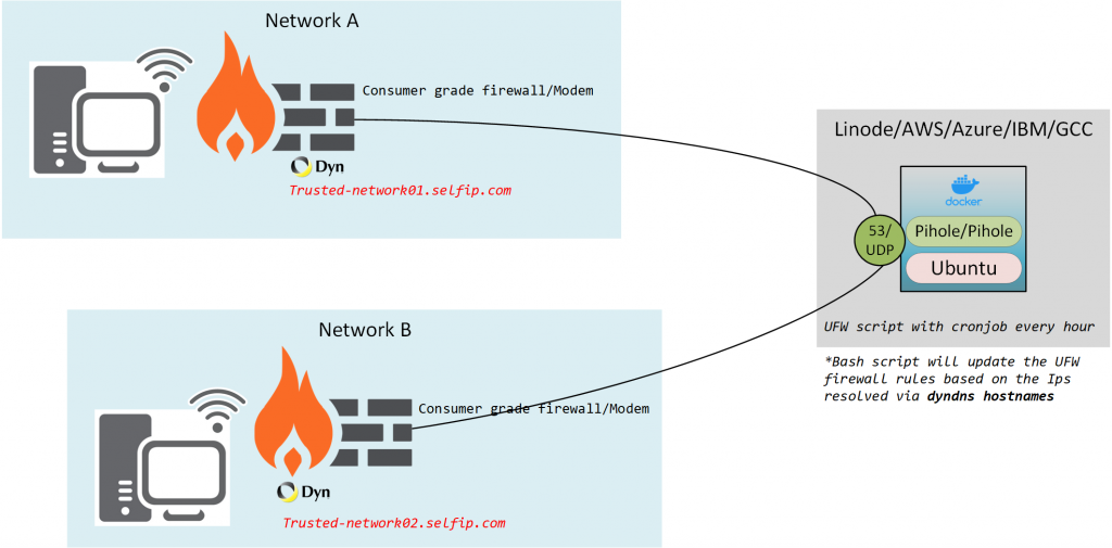
Let me address the question of why I decided to put a DNS server (Pihole) exposed to the internet (not fully open but still).
I needed/wanted to set up an Umbrella/NextDNS/CF type DNS server that’s publicly accessible but secured to certain IP addresses.
Sure NextDNS is an option and its cheap with similar features, but i wanted roll my own solution so i can learn a few things along the way
I can easily set this up for my family members with minimal technical knowledge and unable to deal with another extra device (Raspberry pi) plugged into their home network.
This will also serve as a quick and dirty guide on how to use Docker compose and address some Issues with Running Pi-hole, Docker with UFW on Ubuntu 20.x
So lets get stahhhted…….
Scope
- Setup Pi-hole as a docker container on a VM
- Enable IPV6 support
- Setup UFW rules to prune traffic and a cronjob to handle the rules to update with the dynamic WAN IPs
- Deploy and test
What we need
- Linux VM (Ubuntu, Hardened BSD, etc)
- Docker and Docker Compose
- Dynamic DNS service to track the changing IP (Dyndns,no-Ip, etc)
Deployment
Setup Dynamic DNS solution to track your Dynamic WAN IP
for this demo, we are going to use DynDNS since I already own a paid account and its supported on most platforms (Routers, UTMs, NAS devices, IP camera-DVRs, etc)
Use some google-fu there are multiple ways to do this without having to pay for the service, all we need is a DNS record that's up-to-date with your current Public IP address.
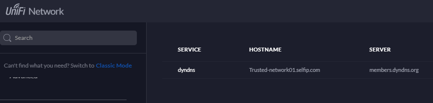
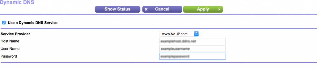
For Network A and Network B, I’m going to use the routers built-in DDNS update features
Network A gateway – UDM Pro
Network B Gateway – Netgear R6230
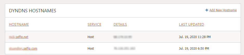
Confirmation
Setup the VM with Docker-compose
Pick your service provider, you can and should be able to use a free tier VM for this since its just DNS
- Linode
- AWS lightsail
- IBM cloud
- Oracle cloud
- Google Compute
- Digital Ocean droplet
Make sure you have a dedicated (static) IPv4 and IPv6 address attached to the resource
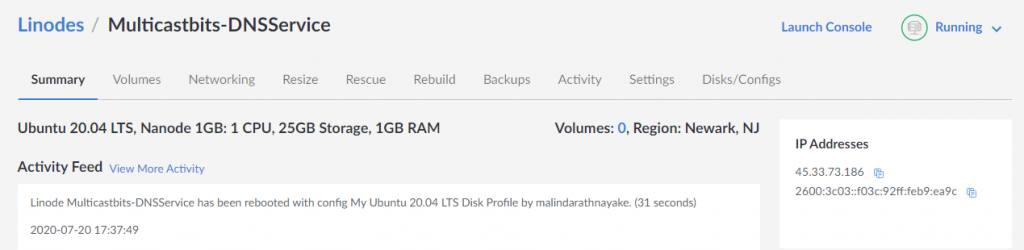
For this deployment, I’m going to use a Linode – Nanode, due to their native IPv6 support and cause I prefer their platform for personal projects
Setup your Linode VM – Getting started Guide
SSH in to the VM or use weblish console
Update your packages and sources
sudo apt-get update
install Docker and Docker Compose
Assuming you already have SSH access to the VM with a static IPv4 and IPv6 address
Guide to installing Docker Engine on Ubuntu
Guide to Installing Docker-Compose
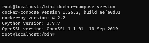
Once you have this setup confirm the docker setup
docker-compose version
Setup the Pi-hole Docker Image
Lets Configure the docker networking side to fit our Needs
Create a Seperate Bridge network for the Pi-hole container
I guess you could use the default bridge network, but I like to create one to keep things organized and this way this service can be isolated from the other containers I have
docker network create --ipv6 --driver bridge --subnet "fd01::/64" Piholev6
verification
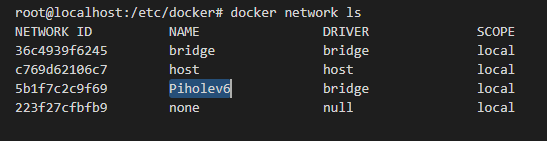
We will use this network later in docker compose
With the new ubuntu version 20.x, Systemd will start a local DNS stub client that runs on 127.0.0.53:53
which will prevent the container from starting. because Pi-hole binds to the same port UDP 53
we could disable the service but that breaks DNS resolution on the VM causing more headaches and pain for automation and updates
After some google fu and trickering around this this is the workaround i found.
- Disable the stub-listener
- Change the symlink to the /etc/resolved.conf to /run/systemd/resolve/resolv.conf
- push the external name servers so the VM won’t look at loopback to resolve DNS
- Restart systemd-resolved
Resolving Conflicts with the systemd-resolved stub listener
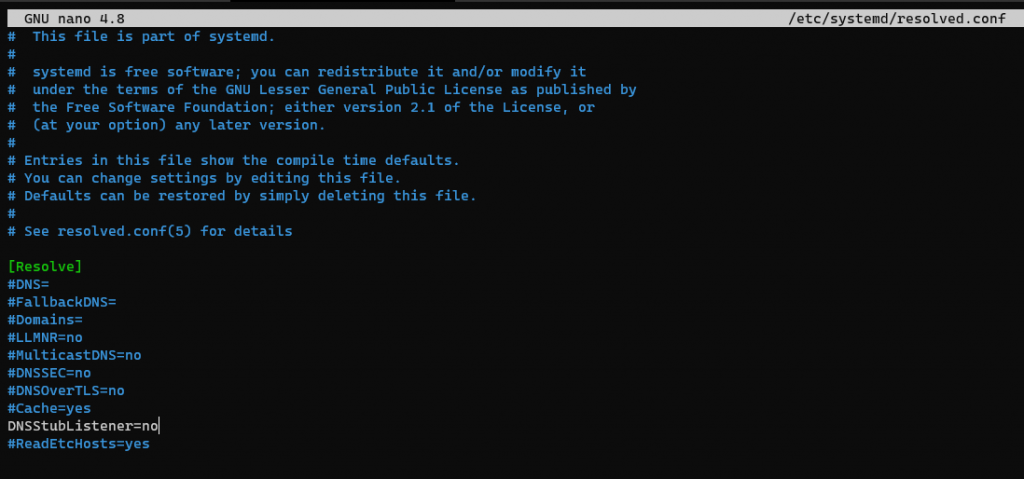
We need to disable the stub listener thats bound to port 53, as i mentioned before this breaks the local dns resolution we will fix it in a bit.
sudo nano /etc/systemd/resolved.conf
Find and uncomment the line “DNSStubListener=yes” and change it to “no”
After this we need to push the external DNS servers to the box, this setting is stored on the following file
/etc/resolv.conf
#     DO NOT EDIT THIS FILE BY HAND -- YOUR CHANGES WILL BE OVERWRITTEN
# 127.0.0.53 is the systemd-resolved stub resolver.
# run "systemd-resolve --status" to see details about the actual nameservers.

nameserver 127.0.0.53
But we cant manually update this file with out own DNS servers, lets investigate
ls -l /etc/resolv.conf

its a symlink to the another system file
/run/systemd/resolve/stub-resolv.conf
When you take a look at the directory where that file resides, there are two files
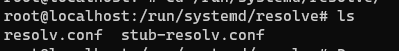
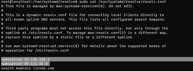
When you look at the other file you will see that /run/systemd/resolve/resolv.conf is the one which really is carrying the external name servers
You still can’t manually edit This file, and it gets updated by whatever the IPs provided as DNS servers via DHCP. netplan will dictate the IPs based on the static DNS servers you configure on Netplan YAML file
i can see there two entries, and they are the default Linode DNS servers discovered via DHCP, I’m going to keep them as is, since they are good enough for my use case
If you want to use your own servers here – Follow this guide
Lets change the symlink to this file instead of the stub-resolve.conf
$ sudo ln -sf /run/systemd/resolve/resolv.conf /etc/resolv.conf
Now that its pointing to the right file

Lets restart the systemd-resolved
systemctl restart systemd-resolved
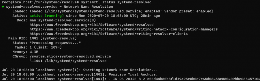
Now you can resolve DNS and install packages, etc
Docker compose script file for the PI-Hole
sudo mkdir /Docker_Images/
sudo mkdir /Docker_Images/Piholev6/
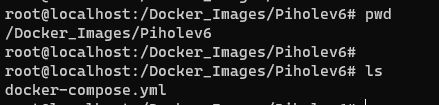
Lets navigate to this directory and start setting up our environment
nano /Docker_Images/Piholev6/docker-compose.yml
version: '3.4'
services:

   Pihole:
    container_name: pihole_v6
    image: pihole/pihole:latest
    hostname: Multicastbits-DNSService
    ports:
      - "53:53/tcp"
      - "53:53/udp"
      - "8080:80/tcp"
      - "4343:443/tcp"
    environment:
      TZ: America/New_York
      DNS1: 1.1.1.1
      DNS2: 8.8.8.8
      WEBPASSWORD: F1ghtm4_Keng3n4sura
      ServerIP: 45.33.73.186
      enable_ipv6: "true"
      ServerIPv6: 2600:3c03::f03c:92ff:feb9:ea9c
    volumes:
       - '${ROOT}/pihole/etc-pihole/:/etc/pihole/'
       - '${ROOT}/pihole/etc-dnsmasq.d/:/etc/dnsmasq.d/'
    dns:
      - 127.0.0.1
      - 1.1.1.1
    cap_add:
      - NET_ADMIN
    restart: always

networks:
  default:
    external:
      name: Piholev6
networks:
  default:
    external:
      name: Piholev6
Lets break this down a littlebit
- Version – Declare Docker compose version
- container_name – This is the name of the container on the docker container registry
- image – What image to pull from the Docker Hub
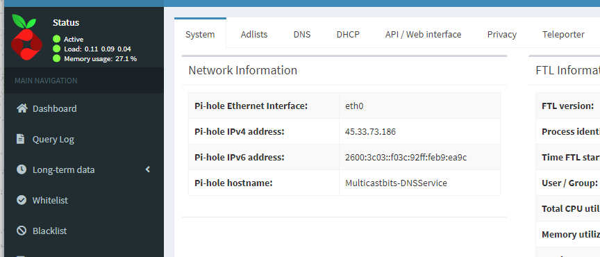
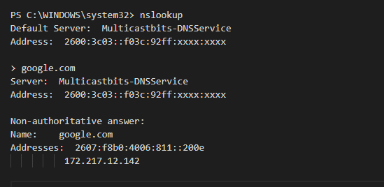
- hostname – This is the host-name for the Docker container – this name will show up on your lookup when you are using this Pi-hole
- ports – What ports should be NATed via the Docker Bridge to the host VM
- TZ – Time Zone
- DNS1 – DNS server used with in the image
- DNS2 – DNS server used with in the image
- WEBPASSWORD – Password for the Pi-Hole web console
- ServerIP – Use the IPv4 address assigned to the VMs network interface(You need this for the Pi-Hole to respond on the IP for DNS queries)
- IPv6 – Enable Disable IPv6 support
- ServerIPv6 – Use the IPv4 address assigned to the VMs network interface (You need this for the Pi-Hole to respond on the IP for DNS queries)
- volumes – These volumes will hold the configuration data so the container settings and historical data will persist reboots
- cap_add:- NET_ADMIN – Add Linux capabilities to edit the network stack – link
- restart: always – This will make sure the container gets restarted every time the VM boots up – Link
- networks:default:external:name: Piholev6 – Set the container to use the network bridge we created before
Now lets bring up the Docker container
docker-compose up -d
-d switch will bring up the Docker container in the background
Run ‘Docker ps’ to confirm
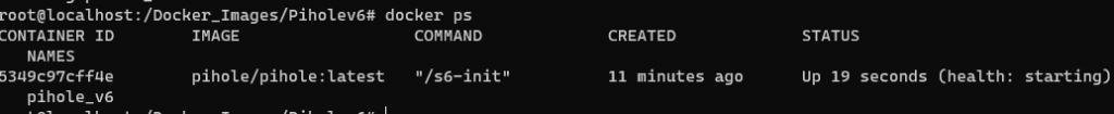
Now you can access the web interface and use the Pihole
verifying its using the bridge network you created
Grab the network ID for the bridge network we create before and use the inspect switch to check the config
docker network ls
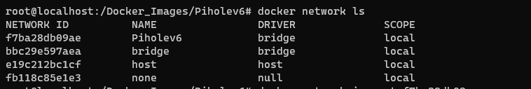
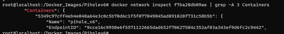
docker network inspect f7ba28db09ae
This will bring up the full configuration for the Linux bridge we created and the containers attached to the bridge will be visible under the “Containers”: tag
Testing
I manually configured my workstations primary DNS to the Pi-Hole IPs
Updating the docker Image
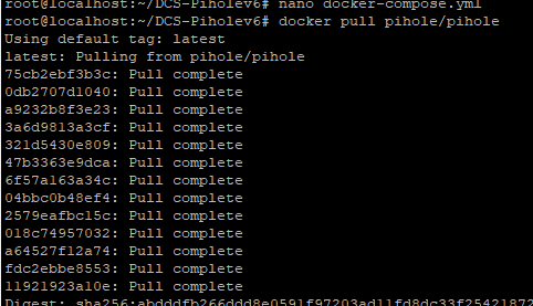
Pull the new image from the Registry
docker pull pihole/pihole
Take down the current container
Run the new container

Your settings will persist this update
Securing the install
now that we have a working Pi-Hole with IPv6 enabled, we can login and configure the Pihole server and resolve DNS as needed
but this is open to the public internet and will fall victim to DNS reflection attacks, etc
lets set up firewall rules and open up relevant ports (DNS, SSH, HTTPS) to the relevant IP addresses before we proceed
Disable IPtables from the docker daemon
Ubuntu uses UFW (uncomplicated firewall) as an obfuscation layer to make things easier for operators, but by default, Docker will open ports using IPtables with higher precedence, Rules added via UFW doesn’t take effect
So we need to tell docker not to do this when launching a container so we can manage the firewall rules via UFW
This file may not exist already if so nano will create it for you
sudo nano /etc/docker/daemon.json
Add the following lines to the file
{
"iptables": false
}
restart the docker services
sudo systemctl restart docker
now doing this might disrupt communication with the container until we allow them back in using UFW commands, so keep that in mind.
Automatically updating Firewall Rules based on the DYN DNS Host records
we are going to create a shell script and run it every hour using crontab
Shell Script Dry run
- Get the IP from the DYNDNS Host records
- remove/Cleanup existing rules
- Add Default deny Rules
- Add allow rules using the resolved IPs as the source
Dynamic IP addresses are updated on the following DNS records
- trusted-Network01.selfip.net
- trusted-Network02.selfip.net
Lets start by creating the script file under /bin/*
sudo touch /bin/PIHolefwruleupdate.sh
sudo chmod +x /bin/PIHolefwruleupdate.sh
sudo nano /bin/PIHolefwruleupdate.sh
now lets build the script
#!/bin/bash
PATH=/sbin:/bin:/usr/sbin:/usr/bin
now=$(date +"%m/%d/%T")
DYNDNSNetwork01="trusted-Network01.selfip.net"
DYNDNSNetwork02="trusted-Network02.selfip.com"
#Get the network IP using dig
Network01_CurrentIP=`dig +short $DYNDNSNetwork01`
Network02_CurrentIP=`dig +short $DYNDNSNetwork02`
echo "-----------------------------------------------------------------"
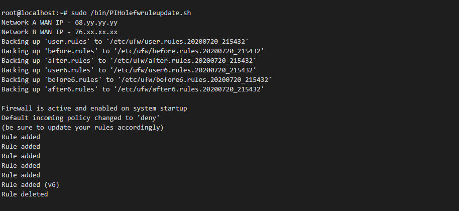
echo Network A WAN IP $Network01_CurrentIP
echo Network B WAN IP $Network02_CurrentIP
echo "Script Run time : $now"
echo "-----------------------------------------------------------------"
#update firewall Rules
#reset firewall rules
#
sudo ufw --force reset
#
#Re-enable Firewall
#
sudo ufw --force enable
#
#Enable inbound default Deny firewall Rules
#
sudo ufw default deny incoming
#
#add allow Rules to the relevant networks
#
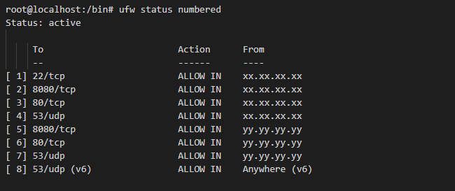
sudo ufw allow from $Network01_CurrentIP to any port 22 proto tcp
sudo ufw allow from $Network01_CurrentIP to any port 8080 proto tcp
sudo ufw allow from $Network01_CurrentIP to any port 53 proto udp
sudo ufw allow from $Network02_CurrentIP to any port 53 proto udp
#add the ipV6 DNS allow all Rule - Working on finding an effective way to lock this down, with IPv6 rick is minimal
sudo ufw allow 53/udp
#find and delete the allow any to any IPv4 Rule for port 53
sudo ufw --force delete $(ufw status numbered | grep '53*.*Anywhere.' | grep -v v6 | awk -F"[][]" '{print $2}')
echo "--------------------end Script------------------------------"
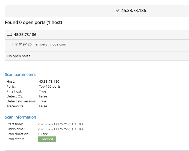
Lets run the script to make sure its working
I used a online port scanner to confirm
Setup Scheduled job with logging
lets use crontab and setup a scheduled job to run this script every hour
Make sure the script is copied to the /bin folder with the executable permissions
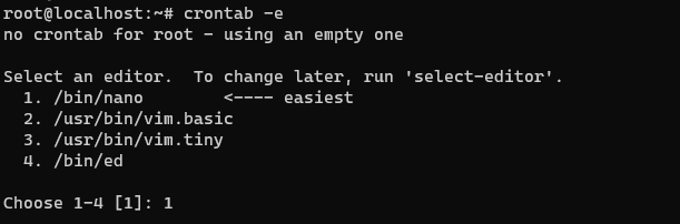
using crontab -e (If you are launching this for the first time it will ask you to pick the editor, I picked Nano)
crontab -e
Add the following line
0 * * * * /bin/PIHolefwruleupdate.sh >> /var/log/PIHolefwruleupdate_Cronoutput.log 2>&1
Lets break this down
0 * * * *
this will run the script every time minutes hit zero which is usually every hour
/bin/PIHolefwruleupdate.sh
Script Path to execute
/var/log/PIHolefwruleupdate_Cronoutput.log 2>&1
Log file with errors captured