IP version 6 with Dual-stack using a Tunnel broker 6in4 – PFSense/ASA -Part 01

If your ISP doesn’t have Native IP version 6 Support with Dual Stack  here is a workaround to get it setup for your home lab enviroment

What you need

> Router/Firewall/UTM that supports IPv6 Tunneling

  • PFsense/OpenSense/VyOS
  • DD-WRT 
  • Cisco ISR
  • Juniper SRX

> Active Account with an Ipv6 Tunnel Broker

      For this example we are going to be using Hurricane Electric Free IPv6 Tunnel Broker

Overview of the setup

For part 1 of this series  we are going to cover the following

  • Dual Stack Setup
  • DHCPV6 configuration and explanation

– Guide –

I used my a Netgate router running PfSense to terminate the 6in4 tunnel.it adds the firewall and monitoring capabilities on your Ipv6 network

Before we begin, we need to make a few adjustments on the firewall

Allow IPv6 Traffic

On new installations of pfSense after 2.1, IPv6 traffic is allowed by default. If the configuration on the firewall has been upgraded from older versions, then IPv6 would still be blocked. To enable IPv6 traffic on PFsense, perform the following:

  • Navigate to System > Advanced on the Networking tab
  • Check Allow IPv6 if not already checked
  • Click Save

Allow ICMP

ICMP echo requests must be allowed on the WAN address that is terminating the tunnel to ensure that it is online and reachable.

Firewall> Rules > WAN
Create a regular tunnel.

Enter your IPv4 address as the tunnel’s endpoint address.

Note – After entering your IPv4 address, the website will check to make sure that it can ping your machine. If it cannot ping your machine, you will get an error like the one below:

You can access the tunnel information from the accounts page

While you are here go to “Advance Tab” and setup an “Update key”. (We need it later)

Create and Assign the GIF Interface

Next, create the interface for the GIF tunnel in pfSense. Complete the fields with the corresponding information from the tunnel broker configuration summary.

  • Navigate to Interfaces > (assign) on the GIF tab.
  • Click fa-plus Add to add a new entry.
  • Set the Parent Interface to the WAN where the tunnel terminates. This would be the WAN which has the Client IPv4 Address on the tunnel broker.
  • Set the GIF Remote Address in pfSense to the Server IPv4 Address on the summary.
  • Set the GIF Tunnel Local Address in pfSense to the Client IPv6 Address on the summary.
  • Set the GIF Tunnel Remote Address in pfSense to the Server IPv6 Address on the summary, along the with prefix length (typically / 64).
  • Leave remaining options blank or unchecked.
  • Enter a Description.
  • Click Save.

Example GIF Tunnel.

Assign GIF Interface

Click fa-plus on Interfaces > (Assignments)

choose the GIF interface to be used for an OPT interface. In this example, the OPT interface has been renamed WAN_HP_NET_IPv6. Click Save and Apply Changes if they appear.


Configure OPT Interface

With the OPT interface assigned, Click on the OPT interface from the Interfaces menu to enable it  Keep IPv6 Configuration Type set to None.

Setup the IPv6 Gateway

When the interface is configured as listed above, a dynamic IPv6 gateway is added automatically, but it is not yet marked as default.

  • Navigate to System > Routing
  • Edit the dynamic IPv6 gateway with the same name as the IPv6 WAN created above.
  • Check Default Gateway.
  • Click Save.
  • Click Apply Changes.
 
Status > Gateways to view the gateway status. The gateway will show as “Online” if the configuration is successful

Set Up the LAN Interface for IPv6

The LAN interface may be configured for static IPv6 network. The network used for IPv6 addressing on the LAN Interface is an address in the Routed /64 or /48 subnet assigned by the tunnel broker.

  • The Routed /64 or /48 is the basis for the IPv6 Address field

For this exercise we are going to use ::1 for the LAN interface IP from the Prefixes provided above

Routed /64 : 2001:470:1f07:79a::/64

Interface IP – 2001:470:1f07:79a::1

Set Up DHCPv6 and RA (Router Advertisements)

Now that we have the tunnel up and running we need to make sure devices behind the lan interface can get a IPv6 address

There are couple of ways to handle the addressing

Sateless Auto Address Configuration (SLAAC)

SLAAC just means Stateless Auto Address Configuration, but it shouldn’t be confused with Stateless DHCPv6. In fact, we are talking about two different approaches.

SLAAC is the simplest way to give an IPv6 address to a client, because it exclusively rely on Neighbor Discovery Protocol. This protocol, that we simply call NDP, allows devices on a network to discover their Layer 3 neighbors. We use it to retrieve the layer 2 reachability information, like ARP, and to find out routers on the network.

When a device comes online, it sends a Router Solicitation message. It’s basically asking “Are there some routers out there?”. If we have a router on the same network, that router will reply with a Router Advertisement (RA) message. Using this message, the router will tell the client some information about the network:

  • Who is the default gateway (the link-local address of the router itself)
  • What is the global unicast prefix (for example, 2001:DB8:ACAD:10::/64)

With these information, the client is going to create a new global unicast address using the EUI-64 technique. Now the client has an IP address from the global unicast prefix range of the router, and that address is valid over the Internet.

This method is extremely simple, and requires virtually no configuration. However, we can’t centralize it and we cannot specify further information, such as DNS settings. To do that, we need to use a DHCPv6 technique

Just like IP v4 we need to setup DHCP for the IPv6 range for the devices behind the firewall to use SLAAT

Stateless DHCPv6

Stateless DHCPv6 brings to the picture the DHCPv6 protocol. With this approach, we still use SLAAC to obtain reachability information, and we use DHCPv6 for extra items.

The client always starts with a Router Solicitation, and the router on the segment responds with a Router Advertisement. This time, the Router Advertisement has a flag called other-config set to 1. Once the client receives the message, it will still use SLAAC to craft its own IPv6 address. However, the flag tells the client to do something more.

After the SLAAC process succeed, the client will craft a DHCPv6 request and send it through the network. A DHCPv6 server will eventually reply with all the extra information we needed, such as DNS server or domain name.

This approach is called stateless since the DHCPv6 server does not manage any lease for the clients. Instead, it just gives extra information as needed.

Configuring IPv6 Router Advertisements

Router Advertisements (RA) tell an IPv6 network not only which routers are available to reach other networks, but also tell clients how to obtain an IPv6 address. These options are configured per-interface and work similar to and/or in conjunction with DHCPv6.

DHCPv6 is not able to send clients a router for use as a gateway as is traditionally done with IPv4 DHCP. The task of announcing gateways falls to RA.

Operating Mode: Controls how clients behave. All modes advertise this firewall as a router for IPv6. The following modes are available:

  • Router Only: Clients will need to set addresses statically
  • Unmanaged: Client addresses obtained only via Stateless Address Autoconfiguration (SLAAC).
  • Managed: Client addresses assigned only via DHCPv6.
  • Assisted: Client addresses assigned by either DHCPv6 or SLAAC (or both).

Enable DHCPv6 Server on the interface

Setup IPv6 DNS Addresses

we are going to use cloud-flare DNS (At the time of writing CF is rated as the fastest resolver by Thousandeyes.com)

https://developers.cloudflare.com/1.1.1.1/setting-up-1.1.1.1/

1.1.1.1

  • 2606:4700:4700::1111
  • 2606:4700:4700::1001

Keeping your Tunnel endpoint Address Updated with your Dynamic IP

This only applies if you have a dynamic IPv4 from your ISP

As you may remember from our first step when registering the 6in4 tunnel on the website we had to enter our Public IP and enable ICMP

We need to make sure we keep this updated when our IP changes ovetime

There are few ways to accomplish this

  • Use PFsense DynDNS feature 

dnsomatic.com  is wonderful free service to update your dynamic IP on multiple locations, i used this because if needed i have the freedom to change routers/firewalls with out messing up my config (Im using a one of my RasPi’s to update DNS-O-Matic)

im working on another article for this, will link it to this section ASAP


Few Notes –

Android OS, Chrome OS still doesn’t support DHCPv6

Mac OSX and windows 10, Server 2016 uses and prefers Ipv6

Check the windows firewall rules if you have issues with NAT rules and manually update rules

Your MTU will drop-down since you are sending the IPv6 headers encapsulated in the Ipv4 packets.Personally i have no issues with my Ipv6 network Behind a spectrum DOCSIS modem. but this may cause issues depending on your ISP ie : CGNat

Here is a good write up https://jamesdobson.name/post/mtu/


Part 2

With Part two of this series we will use an ASA for IPv6 using the PFsense router as an tunnel-endpoint

Example Network

Link spotlight

– Understanding IPv6 EUI-64 Bit Address

– IPv6 Stateless Auto Configuration

– Configure the ASA to Pass IPv6 Traffic

– Setup IPv6 TunnelBroker – NetGate

– ipv6-at-home Part 1 | Part II | Part III

Until next time….

Install OpenVPN on fireTV (no root required) for NORD (MAC, Windows, Linux)


DISCLAIMER: No copyright infringement intended. This article is for entertainment and educational purposes only,


Alright!! now that’s out of the way I’m going to keep this short and simple 


Scope : – 

Install OpenVPN client
import profile with username and password
connect to your preferred VPN server


Use case : – 

  • Secure your fireTV traffic using any OpenVPN supported VPN services=
  • Connect to your home file server/NAS and stream files when traveling via your FireTV or Firestick using your own VPN server (not covered in this article)
  • Watch Streaming services when traveling using your own VPN server (not covered in this article)


Guide :- 


Project Summary 

Hardware – FireTV 4K Latest firmware 

Platform – Windows 10 Enterprise

in this guide im using ADB to install OpenVPN client on my fireTV and use that to connect to the NORDVPN service

All Project files are located on C:NoRDVPN


Files Needed (Please download these files to your workstation before proceeding)

OpenVPN client APK – http://plai.de/android/

NORDVPN OpenVPN configuration files – https://nordvpn.com/ovpn/

ADBLink – http://jocala.com

01. Enable Developer mode on Fire tv 

http://www.aftvnews.com/how-to-enable-adb-debugging-on-an-amazon-fire-tv-or-fire-tv-stick/

  1. From the Fire TV or Fire TV Stick’s home screen, scroll to “Settings”.
  2. Next, scroll to the right and select “Device”.
  3. Next, scroll down and select “Developer options”.
  4. Then select “ADB debugging” to turn the option to “ON”.
 
02. Install OpenVPN client via the network using ADBLInk
 
Install the ADBlink program
 
Download URL – http://jocala.com
 
Create Device profile and connect 
 
Launch ADBLink and click on “New”
 
 
Fill out the information 
 
Notes – 
 
Address  – this is the IP assigned to your FireTV you can get this from the fireTV Network status page under 
 
“Settings”.> “System”.> “About” > “Network”
 
 
You can also get this information from your ARP table, DHCP leases on your DHCP server, etc 


Leave everything else with default values and save the profile
 
Install APK using ADBLINK
 
 
Browse to the location you download all files to and select the OpenVPN APk file 
 
In this guide the location is “C:NoRDVPN”
After a successful install, you will be greeted with the following dialog box 
02. Configure and copy(ADB Push) OVPN configuration files
 
this step is very important
 
02-01 Create Login configuration files
 
Under the same folder where you downloaded files Example – C:NoRDVPN
 
create a text file with the following name – login.conf
 
Edit the file with your favorite text editor 


Enter your NORDVPN credentials in two separate lines (Email address and password)


Save Changes
 
 
02-02 Edit the VPN configuration file
Open the VPN configuration files in my case, I picked a US server so my filename is 
 
us226.nordvpn.com.udp1194.ovpn
File the line that reads “auth-user-pass” and replace it with “auth-user-pass login.conf
Save Changes
 
02. Push configuration files to the FireTV
 
 
  • Click on “File Manager” on adbLink
               Notes – By Default, it will connect to the root of the SDcard on your FireTV 
  • Create a folder (I’m going to call it NORD_VPN)
 
Find the created “NORD_VPN” folder and double click on it via the left window pane 
Click on “Push”
 
 
Browse to the folder (C:/NoRDVPN) and select the two configuration files 
 
Note – 
 
Use Shift to select multiple files
 
Files will be pushed out to the FireTV as soon as you select Choose


Now we are done with the work from your workstation
 
By the time you reach this step you will have completed the following 
 
  • Installed OpenVPN on the FireTV system
  • Customized the VPN configuration files
  • Copied the VPN configuration files to the Root of the SDcard on the FireTV system
Note – Next steps are really simple and you only need the fireTV remote to complete these
 
03. Import VPN profile on FireTV and connect
 
 
Browse to your Apps and Games > See All 
 

Select and launch OpenVPN Client

Use the + sign to add a profile 

Click Import

Browse and Select the ovpn configuration file using the browser 


Click on the imported VPN profile to initiate the connection 
Under the “Settings” Tab make sure “use System proxy” is enabled
Now your fireTV is routing traffic via the VPN 
 
This is the only outbound connection from the FireTV connecting to the NORDVPN server IP via openVPN port UDP 1194
 
You can find this IP in the configuration file or by going to the OpenVPN logs Tab
 
Until next time….Stay Awesome Internetz : ) 

Server 2016 Data De-duplication Report – Powershell

I put together this crude little script to send out a report on a  daily basis

it’s not that fancy but its functional 

I’m working on the second revision with an HTML body, lists of corrupted files, Resource usage, more features will be added as I dive further into Dedupe CMDlets.

https://technet.microsoft.com/en-us/library/hh848450.aspx

Link to the Script – Dedupe_report.ps1

https://dl.dropboxusercontent.com/s/bltp675prlz1slo/Dedupe_report_Rev2_pub.txt

If you have any suggestions for improvements please comment and share with everyone

# Malinda Ratnayake | 2016
# Can only be run on Windows Server 2012 R2
#
# Get the date and set the variable
$Now = Get-Date
# Import the cmdlets
Import-Module Deduplication
#
$logFile01 = "C:_ScriptsLogsDedupe_Report.txt"
#
# Get the cluster vip and set to variable
$HostName = (Get-WmiObject win32_computersystem).DNSHostName+"."+(Get-WmiObject win32_computersystem).Domain
#
#$OS = Get-Host {$_.WindowsProductName}
#
# delete previous days check
del $logFile01
#
Out-File "$logFile01" -Encoding ASCII
Add-Content $logFile01 "Dedupication Report for $HostName" -Encoding ASCII
Add-Content $logFile01 "`n$Now" -Encoding ASCII
Add-Content $logFile01 "`n" -Encoding ASCII
#
# Get-DedupJob
Add-Content $logFile01 "Deduplication job Queue" -Encoding ASCII
Add-Content $logFile01 "__________________________________________________________________________" -Encoding ASCII
Get-DedupJob | Format-Table -AutoSize | Out-File -append  -Encoding ASCII $logFile01
Add-Content $logFile01 "`n" -Encoding ASCII
#
# Get-DedupSchedule
Add-Content $logFile01 "Deduplication Schedule" -Encoding ASCII
Add-Content $logFile01 "__________________________________________________________________________" -Encoding ASCII
Get-DedupSchedule | Format-Table -AutoSize | Out-File -append  -Encoding ASCII $logFile01
#
#Last Optimization Result and time
Add-Content $logFile01 "Last Optimization Result and time" -Encoding ASCII
Add-Content $logFile01 "__________________________________________________________________________" -Encoding ASCII
Get-DedupStatus | Select-Object  LastOptimizationTime ,LastOptimizationResultMessage | Format-Table -Wrap | Out-File -append  -Encoding ASCII $logFile01
#
#
#Last Garbage Collection Result and Time
Add-Content $logFile01 "Last Garbage Collection Result and Time" -Encoding ASCII
Add-Content $logFile01 "__________________________________________________________________________" -Encoding ASCII
Get-DedupStatus | Select-Object LastGarbageCollectionTime ,LastGarbageCollectionResultMessage | Format-Table -Wrap | Out-File -append  -Encoding ASCII $logFile01
#
# Get-DedupVolume
$DedupVolumeLetter = Get-DedupVolume | select -ExpandProperty Volume
Add-Content $logFile01 "Deduplication Enabled Volumes" -Encoding ASCII
Add-Content $logFile01 "__________________________________________________________________________" -Encoding ASCII
Get-DedupVolume | Format-Table -AutoSize | Out-File -append  -Encoding ASCII $logFile01
Add-Content $logFile01 "Volume $DedupVolumeLetter Details -  " -Encoding ASCII
Get-DedupVolume | FL | Out-File -append  -Encoding ASCII $logFile01
Add-Content $logFile01 "`n" -Encoding ASCII
#
# Get-DedupStatus
Add-Content $logFile01 "Deduplication Summary" -Encoding ASCII
Add-Content $logFile01 "__________________________________________________________________________" -Encoding ASCII
Get-DedupStatus | Format-Table -AutoSize | Out-File -append  -Encoding ASCII $logFile01
Add-Content $logFile01 "Deduplication Status Details" -Encoding ASCII
Add-Content $logFile01 "__________________________________________________________________________" -Encoding ASCII
Get-DedupStatus | FL | Out-File -append  -Encoding ASCII $logFile01
Add-Content $logFile01 "`n" -Encoding ASCII
#
# Get-DedupMetadata
Add-Content $logFile01 "Deduplication MetaData" -Encoding ASCII
Add-Content $logFile01 "__________________________________________________________________________" -Encoding ASCII
Add-Content $logFile01 "note - details about how deduplication processed the data on volume $DedupVolumeLetter " -Encoding ASCII
Get-DedupMetadata | FL | Out-File -append  -Encoding ASCII $logFile01
Add-Content $logFile01 "`n" -Encoding ASCII
#
# Get-Dedupe Events
# Get-Dedupe Events - Resource usage - WIP
Add-Content $logFile01 "Deduplication Events" -Encoding ASCII
Add-Content $logFile01 "__________________________________________________________________________" -Encoding ASCII
Get-WinEvent -MaxEvents 10 -LogName Microsoft-Windows-Deduplication/Diagnostic | where ID -EQ "10243" | FL | Out-File -append  -Encoding ASCII $logFile01
Add-Content $logFile01 "`n" -Encoding ASCII
#
# Change the -To, -From and -SmtpServer values to match your servers.
$Emailbody = Get-Content -Path $logFile01
[string[]]$recipients = "[email protected]"
Send-MailMessage -To $recipients -From [email protected] -subject "File services - Deduplication Report : $HostName " -SmtpServer smtp-relay.gmail.com -Attachments $logFile01

Cisco ASA WAN Failover IP SLA- Guide


We will proceed assuming 

you already configured the ASA with the primary link


Configured the WAN2 on a port with the static IP or DHCP depending on the connection – you should be able to ping the secondary WAN link gateway from the ASA


Note:

Please remove the existing Static Route for the primary WAN link

Configure Route tracking

ASA(config)# route outside 0.0.0.0 0.0.0.0 <ISP 1(WAN1) Gateway> 1 track 1
ASA(config)# route Backup_Wan 0.0.0.0 0.0.0.0 <ISP 2 (WAN2) Gateway> 254


Now lets break it down

Line 01 –  you add the WAN1 route with a administrative distance of 1 and we also include the track 1 statement for the SLA monitor tracking (See below)


Line 02 – with the second line we add the default route for the BackupWan link with a higher administrative distance to make it the secondary link


Examples 

ASA(config)# route outside  0.0.0.0 0.0.0.0 100.100.100.10 1 track 1
ASA(config)# route Backup_Wan  0.0.0.0 0.0.0.0 200.200.200.10 254


Setup SLA monitoring and Route tracking 

ASA(config)# sla monitor 10


Configure the SLA monitor with ID 10

ASA(config-sla-monitor)# type echo protocol ipIcmpEcho 8.8.8.8 interface outside


Configure the monitoring protocol, the target IP for the probe and the interface use

SLA monitor will keep probing the IP we define here and report if its unreachable via the given interface
In this senario im using 8.8.8.8 as the target IP you can use any public IP for monitoring


ASA(config-sla-monitor-echo)# num-packets 4


Number of packets sent to the probe

ASA(config-sla-monitor-echo)# timeout 1000


Timeout value in milliseconds. if you have a slow link as the primary increase the time out accordingly

ASA(config-sla-monitor-echo)# frequency 10


Frequency of the probe in seconds – SLA monitor will probe the IP every 10 seconds

ASA(config)# sla monitor schedule 10 life forever start-time now


Set the ASA to start the SLA monitor now and keep it running for ever

ASA(config)# track 1 rtr 10 reachability


This command will tell the ASA to keep tracking the SLA monitor with the ID:10 and the Default route defined with “Track 1”

if the probe fails to reach the target IP (in this case 8.8.8.8) via the designated interface it will remove the route defined with “Track 1” from the routing table 

The next best possible route in this scenario the backup ISP route with administrative distance of 254 takes its place


Configure dynamic NAT Rules (Important)

nat (inside,<ISP 1(WAN1) Interface Name) source dynamic any interface
nat (inside,<ISP 2(WAN2) Interface Name>) source dynamic any interface


Configure the two NAT statements required so that either interface can provide NATting,

Examples 

nat (inside,outside) source dynamic any interface
nat (inside,Backup_Wan) source dynamic any interface


This method worked well for me personally and keep in mind i’m no Cisco Guru so if i made a mistake or if you feel like there is a better way to do this please leave comment. its all about the community after all

Until next time stay awesome internetz

Reducing Dell PowerEdge (PE) 2950/2900/2800 II/III fan noise – Fan mod + BMC firmware mod (Noob friendly guide)

Dell 2950 III is one of the best bang for the buck servers you can find on Ebaym but there is one problem this server runs very loud by design.

Example (video Credit David Lohle)


I have my lab setup in my room so I had to do something about this.

After wondering around in the OSMA, DRAC and BIOS with no luck, I turned to almighty Google for help.

Turns out Dell decided not to expose the BMC’s fan controller settings to the users. It’s baked in to the firmware.

Reducing the noise involves two mods, hardware and firmware. 

  1. Fan MOD – Lower the Fan speeds to reduce the noise
  2. Firmware mod – Lowering the BMC fan rpm thresholds  


Update: 

I stress tested the server after the mod, check here for details – Dell PE 2950 Stress test

01. Fan MOD – Lower the Fan speeds to reduce the noise

I stumbled upon this post on the “Blind Caveman’s blog”. – http://blindcaveman.wordpress.com/2013/08/23/problem-dell-poweredge-2950-iii-jet-engine-fan-noise/

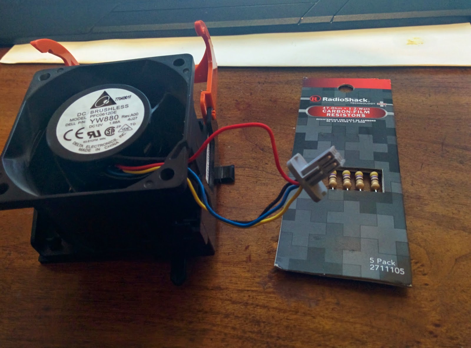
Apparently he had success with adding a 47ohm resistor in line to all 4 intake fans, he has a very comprehensive guide on the mod.

I’m just going to put the summery of what I did. (Props to Caveman for coming up with this solution)


Items you need

  • 4pc of 47ohm ½ watt resistors. (Radio shack $1.49)
  • Heat Shrink. (Radio shack $4.59)
  • Soldering iron.
Note : You can drop the resistor value to increase the fan voltage

10v = 12 ohms
9v = 2020 ohms
8v = 3030 ohms
7v = 42
42 ohms

Fan Mod – Steps

01. Remove the cover.

02. Remove the fan by pulling the orange tabs and gently lifting up.


 03. Remove the wire clip cut the “Red” wire and solder the resistor in line with the wire.


    Red Wire


04. Re-seat the fans back on the server. (be careful not to let it touch the heat sink right next to it)


    Watch out for the Heat-sink

Note:
I just modded the intake fans, OP suggest to mod the PSU fans but I don’t think you need to mess with the power supply fans for 3 reasons. 

        • It’s not going to make a huge difference. (my PE is running below 52db with just the intake fans modded)
        • PSU is Expensive to replace. (on Ebay PSU is around $100 but four Dell 2950 Fans cost less than $10)
        • I believe the PSU units should run very cool and efficient as much as possible.

      —————————————————————————————————————————

      So after the mod, I booted up the server, it was running significantly quieter. BUT… yes there’s a huge but….

      Issue 01 – OSMA Errors and fan speed issues

      The fan speeds were ramping up and down every few minutes. 
      When i monitored the fan speeds via DRAC and it showed an error with the fans failing since the idle rpm is lower than the minimum rpm threshold.


      What is  happening

      the BMC lower the fan RPM after the initial boot, since the resistor is in place the lowest RPM is around 1800 and the default minimum RPM error threshold is 2250rpm so the BMC panics, spins the fans back up to 100%, lower them again since the error is cleared. So on. it was going on in a never ending cycle of annoyingness.

      So after some more google fu. I found a post written by a German “Artificial intelligence researcher” who faced the same issue after he swapped out the dell fans with lower RPM ones and since dell refused to help him fix it, he engineered his own fix for this by modifying the BMC firmware to reduce the minimum rpm threshold (how cool is that).

      His name is Arnuschky – Link | Post link

      His post is well written to the point (Kudos to you sir) but its not very noob friendly. 🙁
      So I’m going to make a step by step guide using his post as reference with few more additions, for anyone who is new to open source and messing with dell firmwares.

      02. Firmware mod – Lowering the BMC fan rpm thresholds


      The solution explained-

      Arnuschky figured out the exact setting in the BMC’s firmware, the check-sums etc to modify the fan rpm thresholds and wrote a very nifty script to help us modify the values on a downloaded firmware file.

      What is BMC (board management controller)

      • Among many other things, fans are controlled by the BMC and the fan curve and all the values are baked in to the firmware.

      • BMC (board management controller) by design will ramp up the RPM of the fans every time you add more hardware to the system such as – Add-on cards, RAM, HDD’s, etc


      What is IPMI

      • Intelligent Platform Management Interface, this tool set can be easily installed on any linux distribution and after you enable IPMI in the BIOS (DRAC interface) you can query sensory data from BMC and configure parameters on the BMC.


      Procedure

      Things you should know –

      • This worked for many people including me. Myself nor anyone involved will not be held responsible for any damages caused by proceeding with the firmware mod.

      • You cannot perform this mod on ESXI. But if you are running a base OS like Redhat/CentOS/Ubuntu you should be good to go.

      • You cannot flash the firmware using a VM (If you know a way please let us know)

      • To modify the firmware you have to be on a Linux server, you can technically flash the modified firmware from windows server. I will add the details later in the post


      Packages required

      • BMC Firmware file – Dell Drivers and support
      • IPMI tools
      • glibc.i686 (If you are on a 64bit OS)

      I have Esxi 5.5 installed on the Dell server so I used a Cent OS 6.4 installation running off a USB stick to do the modifications and flashing


      Enable IPMI on the DRAC interface

      • You can do this by logging in to the DRAC web interface or though the bios screen
      • Press ctrl+E during the post screen to access the DRAC card configuration screen and Enable IPMI

      Setting up IPMI Tools

      yum install OpenIPMI OpenIPMI-tools

      StartEnable the Service

      chkconfig ipmi on
      service ipmi start

      Run the following commands to see if IPMI is working

      ipmitool sdr type Temperature
      Temp             | 01h | ok  |  3.1 | -48 degrees C
      Temp | 02h | ok | 3.2 | -42 degrees C
      Temp | 05h | ok | 10.1 | 40 degrees C
      Temp | 06h | ok | 10.2 | 40 degrees C
      Ambient Temp | 08h | ok | 7.1 | 27 degrees C
      CPU Temp Interf | 76h | ns | 7.1 | Disabled
      ipmitool sdr type Fan
      FAN 1 RPM        | 30h | ok  |  7.1 | 4200 RPM
      FAN 2 RPM | 31h | ok | 7.1 | 4200 RPM
      FAN 3 RPM | 32h | ok | 7.1 | 4200 RPM
      FAN 4 RPM | 33h | ok | 7.1 | 4200 RPM
      FAN 5 RPM | 34h | ok | 7.1 | 4200 RPM
      FAN 6 RPM | 35h | ok | 7.1 | 4200 RPM
      Fan Redundancy | 75h | ok | 7.1 | Fully Redundant

      Install glibc.i686

      yum install glibc.i686

      note:
      Firmware Flash program is 32bit and it will fail with the following warning on 64bit OS

      /lib/ld-linux.so.2: bad ELF interpreter: No such file or directory

      Download the relevant firmware file

      • Visit – http://www.dell.com/support/

      • Enter your service tag 

      • Select OS version – Redhat or any other linux flavor (This will allow you to download the .bin file containing the firmware, this is what we need to modify the values)

      To save you time here’s the link for the Dell PE 2950 II, BMC firmware V2.50 – direct link

      mkdir bmcfwmod 
      cd bmcfwmod #create project directory
      wget "http://downloads.dell.com/FOLDER00928606M/1/2950_ESM_Firmware_4NNNG_LN32_2.50_A00.BIN"

      Set permissions and extract the firmware .bin file

      chmod 755 BMC_FRMW_LX_R223079.BIN                              # make executable
      sudo mkdir bmc_firmware # create dir as root
      sudo ./BMC_FRMW_LX_R223079.BIN --extract bmc_firmware # yes, you have to do this as root! :(
      cd bmc_firmware


      Note : You have to extract the bin file in-order to proceed..
      Above commands will extract the firmware bin file, in to the bmc_firmware folder. 
      Check inside the folder to see if you have a file called /payload/bmcflsh.dat.
      If not that means your system is not compatible with this mod. If yes, please continue.

      Patching the firmware file

      Note:
      You should be in the bmc_firmware directory created above

      Download and run the script

      –no-check-certificate switch is used to get around the cert issue due to the github domain name mismatch

      wget "https://raw.github.com/arnuschky/dell-bmc-firmware/master/adjust-fan-thresholds/dell-adjust-fan-thresholds.py --no-check-certificate"
      chmod 755 dell-adjust-fan-thresholds.py # set permissions
      ./dell-adjust-fan-thresholds.py payload/bmcflsh.dat #execute the py script on the bmcflsh.dat file


      The script will prompt you with the following screen

      Select your server model in this case I selected Dell PowerEdge 2950 = number 3

      Then it will prompt you to select the fans and adjust the threshold.
      On the DRAC interface the intake fans shows up numbered 1-4,
      I edited the values for the fans 1 thorough 4 (Only the intake fans will be effected)

      Setting the value

      When you select the fan number it will ask you to enter the value for the new threshold
      This should be entered in multiples of 75 for example the default value is 2025 which is a 27×75 so the default value is 27
      So to reduce the threshold value you need to enter something lower than 27
      I choose 18 as the value, this will drop my threshold to 1350rpm (18×75=1350)

      Saving the changes

      After editing the appropriate values, enter “W” to write the changes to the firmware as prompted.
      This will update the bmcflsh.dat with the modified values

      Flashing the modified firmware

      If you are on a 64bit OS make sure you have the glibc.i686 package installed

      LD_LIBRARY_PATH=./hapi/opt/dell/dup/lib:$LD_LIBRARY_PATH ./bmcfl32l -i=payload/bmcflsh.dat –f


      This will map the necessary Shared Libraries and execute the bmcfl32l to flash the firmware file

      Fans will rev up and stop for a brief moment during the update, don’t worry it will spool up again in a second.
      You do not need to reboot to see the changes, but do a reboot just in case.
      So there you go, your Dell 2950 should be purring away on the shelf silently.

      Note:
      You should disable the IPMI on DRAC since it is a big security risk.

      Tested for more 24 hours

      Update: Dell PE 2950 Stress test after the mod

      • No noticeable temperature difference with the components 
      • No post errors 
      • No OMSA or DRAC errors 

      Noise Level comparison

      Before the mod

      After the mod

      Its a very long post and its almost morning. so forgive me for any grammar, spelling or formatting mistakes.

      Until next time…….

      Powershell: simple script for port monitoring (SMTP, HTTP, FTP, etc) using “system.net.sockets.tcpclient” class

      Recently we had a requirement to check SMTP of two diffrent servers and run a script if both servers failed. i googled around for the tool but ended up putting together this script.

      Its not the most prettiest but it works, and im sure you guys will make something much better out of it.

      # Define the host names here for the servers that needs to be monitored
      $servers = "relay1.host.com","relay2.host.com"
      # Define port number
      $tcp_port = "25"

      # Loop through each host to get an individual result.
      ForEach($srv in $servers) {

      $tcpClient = New-Object System.Net.Sockets.TCPClient
      $tcpClient.Connect($srv,$tcp_port)

      $connectState = $tcpClient.Connected

      If($connectState -eq $true) {
      Write-Host "$srv is online"
      }
      Else {
      Write-Host "$srv is offline"
      }

      $tcpClient.Dispose()

      }

      If something is wrong or if you think there is a better way please free feel to comment and let everyone know. its all about community after all.

      Update 4/18/2016 –

      Updated the script with the one provided by Donald Gray – Thanks a lot : )

      Exchange 2010 Mailbox PST export – New-MailboxExportRequest

      Remember the Export-Mailbox command on exchange 2007??? The main problem I personally had was the annoying outlook requirement. 
      With the exchange server 2010 service pack 1 release, M$ introduced a new Cmdlet to export mailboxes on the server. And it does not require outlook.
      New-MailboxExportRequest

      Step 01 – Mailbox Import Export Role Assignment
      Grant the user account permissions to export mailboxes (By default no account has the privileges to export mailboxes)
      New-ManagementRoleAssignment -Role “Mailbox Import Export” -User administrator

      Step 02 – Setup the Export File Location
      We need a network share to export files. (Eg – \Exch01PST_export)
      Note:
      The Cmdlet gives an error if you point to a directory directly on the Hardisk (Eg – F:PST_export)
      Create a Shared folder on a serverNAS and grant Exchange Trusted Subsystem user account read/write permissions to the folder
      Exporting Mailbox Items with “New-MailboxExportRequest”

      Supporting Cmdlets that can be used with MailboxExportRequest
      Cmdlet
      Description
      Topic
      Start the process of exporting a mailbox or personal archive to a .pst file. You can create more than one export request per mailbox. Each request must have a unique name.
      Change export request options after the request is created or recover from a failed request.
      Suspend an export request any time after the request is created but before the request reaches the status of Completed.
      Resume an export request that’s suspended or failed.
      Remove fully or partially completed export requests. Completed export requests aren’t automatically cleared. You must use this cmdlet to remove them.
      View general information about an export request.
      View detailed information about an export request.
      In this example
      Shared folder name-  PST_export
      server name- EXCH01
      Share Path –  \Exch01PST_export
      Mailbox – amy.webber

      Folder permissions – 

      For this example we are going to use New-MailboxExportRequest cmdlet with the following parameters :

      -baditemlimit 200 -AcceptLargeDataLoss
      AcceptLargeDataLoss
      The AcceptLargeDataLoss parameter specifies that a large amount of data loss is acceptable if the BadItemLimit is set to 51 or higher. Items are considered corrupted if the item can’t be read from the source database or can’t be written to the target database. Corrupted items won’t be available in the destination mailbox or .pst file.
      baditemlimit
      The BadItemLimit parameter specifies the number of bad items to skip if the request encounters corruption in the mailbox. Use 0 to not skip bad items. The valid input range for this parameter is from 0 through 2147483647. The default value is 0.
      Exporting the Whole Mailbox
      Run the following Cmdlet to initiate the mailbox move request:  New-MailboxExportRequest
      New-MailboxExportRequest -baditemlimit 200 -AcceptLargeDataLoss -Mailbox amy.webber -FilePath \Exch01PST_exportamy.webber.pst

      Exporting the User’s Online Archive
      If you want to export the user’s online archive to .pst, use the –IsArchive parameter.

      New-MailboxExportRequest -baditemlimit 200 -AcceptLargeDataLoss -Mailbox amy.webber  -IsArchive -FilePath \Exch01PST_exportamy.webber-Archive.pst

      Exporting a Specific Folder
      You can export a folder from the users mailbox using the -IncludeFolders parameter
      Eg: inbox folder layout-
      To export the inbox folder
      New-MailboxExportRequest -baditemlimit 200 -AcceptLargeDataLoss -Mailbox amy.webber -IncludeFolders #Inbox# -FilePath \Exch01PST_exportamy.webber.pst
      Checking the Progress of the Mailbox Export Request

      To check the current statues of the mailbox export request use the following cmdlet:
      Get-MailboxExportRequest | Get-MailboxExportRequestStatistics
      People do crazy stuff scripting with this Cmdlet. Look around in the interwebs for some scripts.
      Useful links:
      Until next time…

      Hacking WatchGuard Firebox to Run pfsense- nanoBSD


      Hi Internetz, its been a while…

      So we had an old Firebox X700 laying around in office gathering dust. I saw this forum post about running m0nowall on this device. since pfsense is based on m0nowall, I googled around to find a way to install pfsense on the device and found several threads on pfsense forums. 
      It took me a little while to comb through thousands of posts to find a proper way to go about this. And some more time was spent on troubleshooting the issues I faced during the installation and configuration. So I’m putting everything I found on this post, to save you the time spent googling around. This should work for all the other firebox models as well.

      What you need :

      Hardware

      • Firebox 
      • Female to Female Serial Cable – link
      • 4GB CF Card (We can use 1Gb, 2Gb but personally I would recommend at-least 4GB)
      • CF Card Reader

      Software

      • pfsense NanoBSD
      • physdiskwrite –  Download
      • TeraTerm Pro Web – Enhanced Telnet/SSH2 Client – Download

      The firebox X700

      This is basically a small X86 PC. we have a Intel Celeron CPU running at @1.2Ghz with 512MB Ram. The system boots using a CF card with watchguard firmware
      The custom Intel motherboard used in the device does not include a VGA or a DVI port. we have to use the serial port for all the communications with the device

      There are several methods to run pfsense on this device.

      HDD

      Install PF sense on a PC and Plug the HDD to the firebox.

      This requires a bit more of a effort cause we need to change the boot order on bios. and its kinda hard to find IDE laptop HDD’s these days

      CF card

      This is very straight forward Method. We are basically swapping out the CF card already installed on the device and booting pfsense from it. 


      In this tutorial we are using the CF card method

      Installing PFsense

      • Download the relevant pfsense image


      Since we are using a CF card we need to use the PFsense version built to work on embedded devices.

      NanoBSD version is built specially to be used with CFcards or any other storage media’s that have limited read write life cycle

      Since we are using a 4GB CF card, we are going to use the 4G image

      • Flashing the nanoBSD image to the CF card


      Extract the physdiskwrite program and run the PhysGUI.exe
      This software is written in German i think but operating it is not that hard

      Select the CF card from the list.

      Note : if you are not sure about the disk device ID. use diskpart and determine the disk ID

      Load the ISO file
      Right click on the Disk “Image laden > offnen”

      select the ISO file from the “open file” window
      program will prompt you with the following dialog box


      Select the remove 2GB restriction and click “OK”
      It will warn you about the disk being formatted (I think), click yes to start the disk flashing process. a CMD window will open and show you the progress

      • Installing the CF card on the Firebox

      Once the flashing process is completed, open up the Firebox and Remove the drive cage to gain access to the installed CF Card

      Remove the protective glue and replace the card with the new CF card flashed with pfsense image.

      • Booting up and configuring PFsense

      since Firebox does not have any way to connect to a display or any peripheral ports. We need to use a serial connection for communicating with the device

      Install “teraTerm pro web” program we downloaded earlier.

      I tried using putty and many other telnet clients didn’t work properly

      Open up the terminal window

      Connect the firebox to the PC using the serial cable, and power it up

      Select “Serial” and select the com port the device is connected to and click OK(You can check this in device manager)

        
      Many other tutorials says to change the baud rates. but defaults worked just fine for me
      Since we already flashed the PFsense image to the CF card we do not need to install the OS

      By now on the terminal window you should be having the PF sense configuration details. just as with a normal fresh install.

      It will ask you to setup VLan

      Assign the WAN, LAN, OPT1 interfaces.

      ON X700 interface names are as follows 

      Please refer to pfsense Docs for more info on setting up 


      http://doc.pfsense.org/index.php/Tutorials#Advanced_Tutorials


      After the initial config is completed. you do not need the console cable and Tera Term
      you will be able to access the PFsense via the web-interface and good ol SSH via the LAN IP


      Addtional configuration

      • Enabling the LCD panel

      All firebox units have a LCD panel in front
      We can use the pfsense LCDproc-dev package to enable and display various information

      Install the LCDproc-dev Package via the package Manager

      Go to Services > LCDProc

      Set the settings as follows


      Hope this article helped you guys.Dont forget to leave a comment with your thoughts 

      Sources –

      http://forum.pfsense.org/index.php?board=5.0